Hydraulic Buffer Failures: Root Causes & Preventation
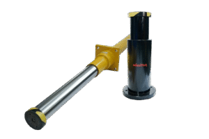
Hydraulic buffer failures in overhead cranes are a critical concern for MSME factories and crane OEMs, often manifesting as unexpected rebound, oil leakage, or complete loss of damping during impact. While these are visible symptoms, the real failure points often originate at the sizing and selection stages, not merely during use or maintenance.
Hydraulic Buffer Failures: Root Causes
Many maintenance teams notice issues like oil leaks or rod misalignment but overlook deeper design flaws. Here are the most common—and often preventable—causes:
- Undersized buffer
- If the buffer's energy absorption capacity is less than the actual impact energy (EEE), it will consistently bottom out or rebound violently, causing damage to the crane structure.
- Improper stroke selection
- Choosing too short a stroke leads to high peak forces during impact, causing residual energy transfer into crane frames and sensitive components.
- Overheating in high-cycle applications
- Frequent impacts cause the buffer oil to heat up, dropping its viscosity and reducing the consistency of damping force—especially in busy steel plants or hot metal operations.
- Misalignment or side loading
- Lateral forces bend the buffer rod or damage seals, causing leakage and potential jamming of the piston.
- Corrosion and seal degradation
- Coastal sites, high-moisture steel plants, and improper material selection result in corrosion or seal failures, leading to poor buffer return and persistent oil leaks.
- Long-term parking compression
- Some buffer designs (e.g., Enidine HD Series) lose bladder pressure or spring force after extended compression, so the rod fails to return fully and may need manual reset or overhaul.
Sizing Stage: How to Prevent Failures
The best way to avoid buffer disasters is at the design and sizing stage. This means:
- Use a robust impact energy formula
- For hydraulic buffers, always use E=1.5×Mass×Velocity2E = 1.5 \times \text{Mass} \times \text{Velocity}^2E=1.5×Mass×Velocity2—not the standard kinetic energy formula. Buffers must absorb peak collision energy, often much higher than average.
- Leverage digital tools
- Try specialized crane buffer calculators, which require crane mass, speed, and sometimes motor power to precisely size buffer stroke, diameter, and absorption specs.
- Select buffers with state-of-the-art features
- Orifice-based hydraulic damping (never spring-only)
- Nitrogen-charged return systems for instant reset after impact
- Compliance with IS3317:2020 or equivalent standards to ensure safety and legal adherence
- Account for harsh environments
- Use corrosion-resistant materials and high-temperature variants for steel plants, ports, and coastal sites.
Maintenance & Early Failure Monitoring
Preventive monitoring and routine care substantially extend buffer life:
- Visual inspections every 6 months: Check for oil leaks, rod misalignment, corrosion, or any physical damage.
- Cycle-based maintenance: Plan to overhaul or replace hydraulic seals after ~250,000 cycles, more often in high-cycle settings.
- Temperature monitoring: Ensure buffer surface temperature stays below 60°C, upgrade to high-temp variants if needed.
- Rod return testing: Fully compress and release the rod—if it doesn’t return instantly, test bladder pressure and oil volume.
- Oil and filter care: Replace hydraulic oil and filters regularly, following manufacturer recommendations to prevent contamination and wear. Keep all buffer and hydraulic system parts clean at every top-off or maintenance interval to minimize dust, water, and particulates.
Design, Sizing, and Field Practices: The Takeaway
The majority of hydraulic buffer failures result from sizing errors, poor selection, or lack of compliance with industry standards, not just user mishandling or skipped maintenance. By starting with accurate calculations, using advanced features, and strictly adhering to a preventive maintenance schedule, manufacturers and operators can dramatically reduce unplanned downtime and costly repairs.